Setup an XBee radio network
In this post you’ll see how to setup a gateway/host capable to communicate with
Xbee microcontroller nodes using the
Zigbee radio protocol.
All activities will be done from a Linux host (Ubuntu), anyway it shouldn’t be too hard to do the same on other OS.
Hardware
For this you’ll need at least the following hardware material:
- 2 or more XBee microcontrollers;
- An Xbee - USB adapter; like this or this;
- An XBee adapter capable to power the XBee device and maybe mountable on a breadboard, like this;
Host’s user permission check
The user on the host computer should have the permissions to access USB and serial devices.
In Ubuntu, the user should be part of the following groups: sudo, plugdev, dialout.
Check for their presence in the list of the groups assigned to the user:
id <user>
uid=1000(<user>) gid=1000(<user>) groups=1000(<user>),4(adm),20(dialout),24(cdrom),27(sudo),30(dip),46(plugdev)
In case one or more group is missing, for example the dialout, add it:
sudo usermod <user> -a -G dialout
After adding one or more group, the safer option is to logout from the desktop and then login again. The id command now should show all expected groups as above.
XBee Software installation
In order to configure the XBee devices, the XCTU application should be installed.
It’s a free, eclipse based tool which enable full control over XBee devices.
After the download, execute the file in order to proceed with the installation.
Beware that there is the need to add execute permission to the file in order to launch it: chmod +x 40002881_S.run.
XBee devices configuration
-
Mount the first XBee device on the USB adapter, and connect the adapter to the host’s USB port. The host should identify the presence of a serial device connected to the USB port and it should load the FTDI serial driver. A serial device connected to the first available USB serial port
ttyUSB0should appear. - Check with the command
dmesgto have a log similar to the one below.[24346.221548] usb 1-2.2: new full-speed USB device number 11 using xhci_hcd [24346.328650] usb 1-2.2: New USB device found, idVendor=0403, idProduct=6015 [24346.328654] usb 1-2.2: New USB device strings: Mfr=1, Product=2, SerialNumber=3 [24346.328657] usb 1-2.2: Product: FT231X USB UART [24346.328660] usb 1-2.2: Manufacturer: FTDI [24346.328662] usb 1-2.2: SerialNumber: DN018U3T [24346.342453] usbcore: registered new interface driver usbserial_generic [24346.342486] usbserial: USB Serial support registered for generic [24346.345488] usbcore: registered new interface driver ftdi_sio [24346.345547] usbserial: USB Serial support registered for FTDI USB Serial Device [24346.345635] ftdi_sio 1-2.2:1.0: FTDI USB Serial Device converter detected [24346.345709] usb 1-2.2: Detected FT-X [24346.345951] usb 1-2.2: FTDI USB Serial Device converter now attached to ttyUSB0 -
Open the XCTU application and select
add a radio moduleoperation. A popup will open, containing the correct pre-selected serial port. See the image below.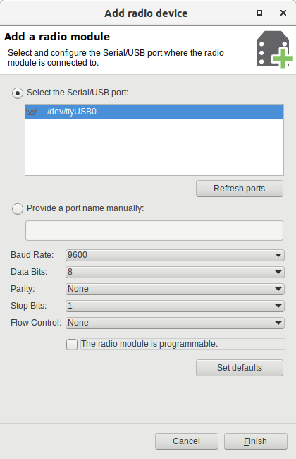
-
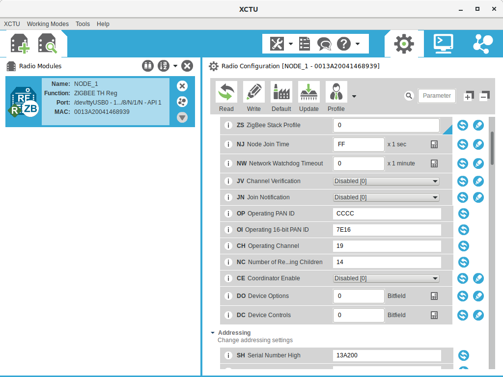
The device is now listed inside a blue box in XCTU’s left panel.
-
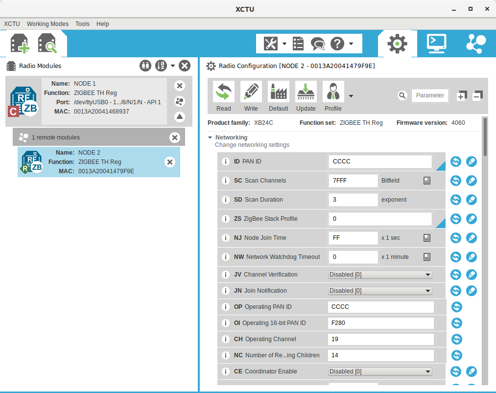
Configure the network; Set the ID PAN ID parameter to an unused value, in order to avoid disturbing other existing networks, for me it’s ok to set it to
CCCC. Always apply any settings pressing the Write button to the right in the parameter row. -
Set the node as
Coordinator; Set the CE parameter Coordinator Enable toEnabled [1]. The configuration should be similar to the image below. Note that the node has now a red C, which means that it is correctly identified as a coordinator node.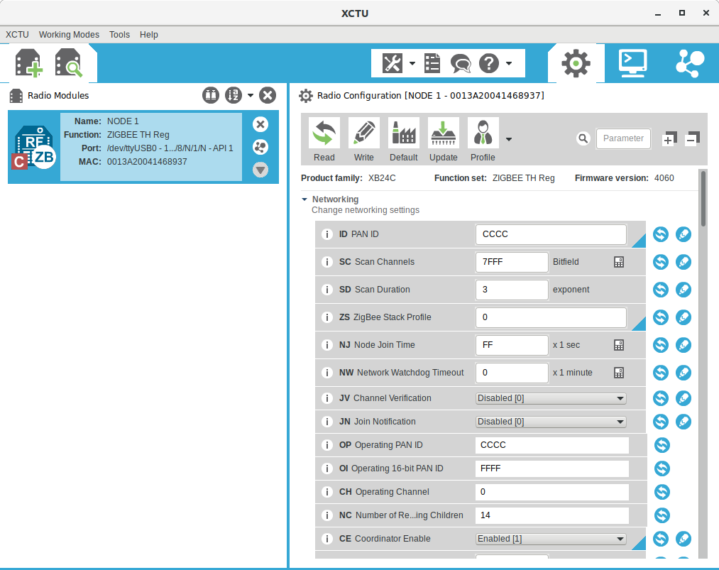
-
Set node name; Set the NI Node identifier parameter to
NODE 1. -
Remove the first device from USB adapter and insert the second. Follow the same steps from 3 to 5 and set up the ID PAN ID to the same value as above. Set node name to
NODE 2setting the NI Node identifier parameter. The second node should have a green R, which means Router. -
Set up the final network configuration, in which the coordinator is connected to the USB adapter and the router is mounted on the other adapter. In this way the host computer will communicate with the Coordinator using the serial port through the USB.
- Discover the devices connected to the radio network: Click on the
discover radio nodesbutton to the right of the blue box containing the first node. The second node should be identified within seconds and it should appear below the first one.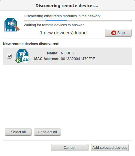
The radio network is now working, and the nodes are both accessible and configurable using XCTU.